
Page 17 - PDF_Flip_Book
P. 17
Rod Machado’s Private/Commercial Pilot Handbook
5-26
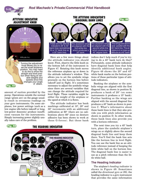
Fig. 48
Here are a few more things about indices don’t help much if you’re try-
the attitude indicator you should ing to do a 45° bank turn do they?
know. First, observe the little knob on Fortunately, some attitude indicators
the bottom left of the instrument in have diagonal bank lines that help
Figure 47. Rotating this knob moves identify additional bank angles.
the reference airplane up or down in Figure 48 shows the 20° and 45°
the attitude indicator’s window. This white bank marks on the bottom por-
allows you to set the symbolic wings tions of these particular types of atti-
precisely on the horizon line before tude indicators.
takeoff and in flight. It’s sometimes Banking the airplane so the sym-
Fig. 47 necessary to adjust the symbolic wings bolic wings are aligned with the first
since there are several variables that diagonal line, as shown in position B,
amount of suction provided by the can change the attitude required for produces a bank of 20° (on some
pump. Operations outside the normal level flight. These variables might be instruments it produces a 15° bank).
range (green arc) on the gauge usual- either the weight of the airplane or Further banking so the wings are
ly result in erroneous readings on the speed at which it is flown. aligned with the second diagonal line
your gyro instruments. On some air- The attitude indicator has bank produces a 45° bank as shown in posi-
planes, low power settings (such as a markings calibrated at 10°, 20° and
tion C. What’s informative about
low engine idle before takeoff or long, 30° increments with an additional
these bank lines is that they also pro-
low-power descents) produce insuffi- calibration at 60° (there are no cali- vide you with pitch information as
cient vacuum for the instruments. brations above 60° since no denture shown in position D. In other words,
Simply increasing power slightly usu- adhesive has been shown to work at these bank lines also provide you
ally takes care of the problem. these G-forces). But these bank
with a horizon reference.
Fig. 49 The next time you try a 45° bank
turn, place the symbolic airplane’s
wings on or slightly above the second
diagonal bank line and keep them
there. You’ll find the bank line acts
like the horizon line in level flight.
You can use the bank line as an atti-
tude reference instead of keeping the
little white ball on the horizon line.
The diagonal bank line is easier to
use as a pitch reference than the lit-
tle white ball.
The Heading Indicator
The airplane’s heading indicator is
shown in Figure 49. Sometimes
called the directional gyro or DG, the
heading indicator is a gyro instrument
that provides the same information